 en
 ori
 alb
 amh
 ara
 arm
 aym
 aze
 bel
 ben
 bos
 bul
 bur
 cs
 dan
 de
 div
 el
 est
 fil
 fin
 fra
 gle
 glg
 grn
 heb
 hi
 hkm
 hrv
 hu
 ice
 id
 it
 jp
 kan
 kin
 kor
 lao
 lav
 lit
 ltz
 lug
 mao
 may
 mlt
 nep
 nl
 nor
 nya
 orm
 per
 pl
 pt
 rom
 ru
 san
 sk
 som
 spa
 srp
 swa
 swe
 tam
 th
 tr
 ukr
 urd
 vie
 wel
 xho
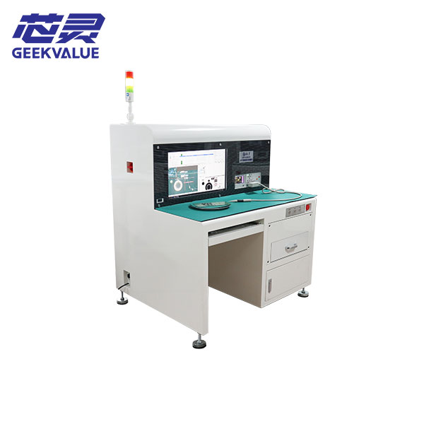
On the FAT-300, the operator places the LCR clips on the component, and the software judges the reading against the programmed criteria. This workflow gives the operator control over probe placement on resistors and capacitors while keeping the judgment and inspection record in the same system. For parts with visible codes, the system can also compare markings on the scanned board image.
The inspection program is built from the BOM, XY coordinates and a scanned image of the first board. Configurable BOM parsing is useful for contract manufacturers who receive a different spreadsheet layout from each customer. Once a program is set up, it can be reused on repeat jobs with the corresponding board revision.
| Test setup | FAT-300 |
|---|---|
| Electrical measurement | Operator-applied clips and a digital LCR bridge |
| Optical checks | Image comparison for visible component markings |
| Program input | BOM, XY data for both board sides and a scanned assembly image |
| Inspection record | Automatic report generation with Excel or PDF export |
Bring a sample BOM and a densely populated assembly to the evaluation. That makes it possible to check the import rules, access for the LCR clips and how the exported report presents exceptions.