 en
 ori
 alb
 amh
 ara
 arm
 aym
 aze
 bel
 ben
 bos
 bul
 bur
 cs
 dan
 de
 div
 el
 est
 fil
 fin
 fra
 gle
 glg
 grn
 heb
 hi
 hkm
 hrv
 hu
 ice
 id
 it
 jp
 kan
 kin
 kor
 lao
 lav
 lit
 ltz
 lug
 mao
 may
 mlt
 nep
 nl
 nor
 nya
 orm
 per
 pl
 pt
 rom
 ru
 san
 sk
 som
 spa
 srp
 swa
 swe
 tam
 th
 tr
 ukr
 urd
 vie
 wel
 xho
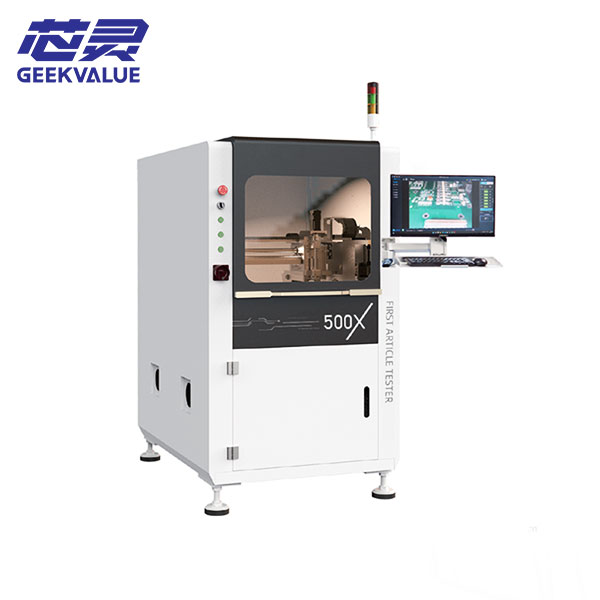
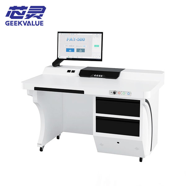
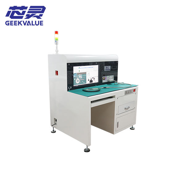
The FAT-400X runs optical inspection and automated flying-probe LCR measurements on the first assembled PCB. Once the test program is set up, the machine moves the probes to the programmed points, records readings and applies the set limits. The optical check covers features such as missing components, package size, polarity and legible IC markings. The resulting first article report records the checks for production release.
| Inspection mode | What to verify on a sample board |
|---|---|
| Optical inspection | Component presence, package outline, polarity and readable markings |
| Automated flying-probe LCR | Access to programmed contact points and measurement repeatability on selected components |
| First article report | How the system records failed checks and points requiring review |
Probe access is worth checking early on a dense assembly. Tall parts, shields and tight spacing can affect which contact points the machine can reach. Send a populated board and a list of the positions you need to verify for an evaluation. Use the same sample to review optical coverage, confirm the probe path and time the programmed inspection sequence.