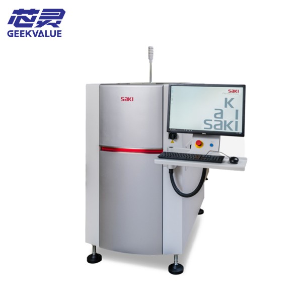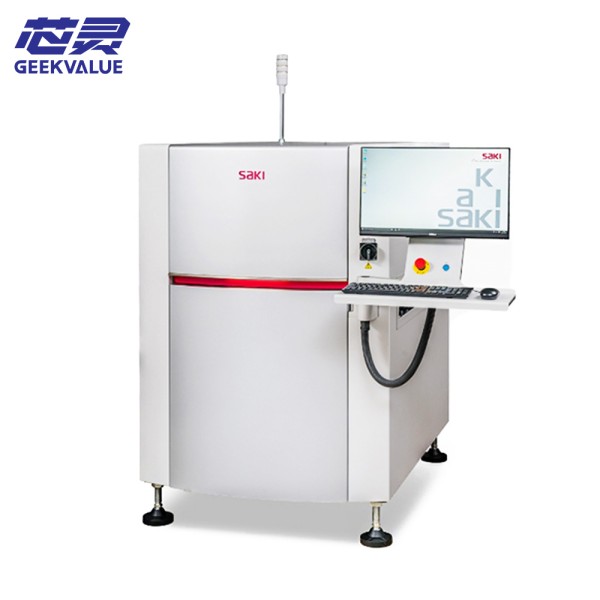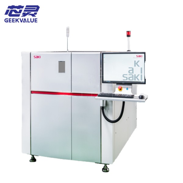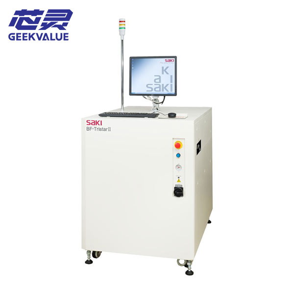
SAKI 3Di-LS3EX is a high-performance 3D automatic optical inspection (AOI) device designed for solder joints, component placement and defect detection of PCB assembly (PCBA). The device uses multi-angle 3D imaging technology, combined with high-precision optical systems and AI algorithms, to quickly detect the welding quality of BGA, QFN, CSP, and SMT components and improve production yield.
2. Main technical specifications
1. Optical system
Detection method: 3D laser scanning + high-resolution color imaging
Light source: multi-angle LED ring light (adjustable brightness)
Camera resolution: up to 12MP (4096×3072 pixels)
Scanning speed: ≤ 0.5 seconds/detection point (depending on configuration)
Minimum detection component size: 01005 (0.4mm × 0.2mm)
Z-axis height measurement accuracy: ±5μm
2. Mechanical system
Maximum PCB size: 510mm × 460mm (larger size can be customized)
Stage movement accuracy: ±5μm
Detection height range: 0~50mm (adjustable)
Motion control: high-precision servo motor + linear guide
3. Precautions for use
1. Safety operating specifications
Optical system protection: Avoid strong light directly hitting the lens and prevent dust from contaminating the optical components.
Mechanical safety: Do not touch the moving parts when the equipment is running to prevent pinching.
2. Daily operation precautions
Power-on sequence:
First turn on the main power supply and wait for the system self-check to complete (about 1 minute).
Start the AOI software and check whether the camera and motion mechanism are normal.
PCB placement requirements:
Ensure that the PCB is flat and warp-free to avoid detection errors.
The positioning fixture must be firmly fixed to prevent PCB movement and misjudgment.
Parameter optimization:
The first detection of a new model requires benchmark calibration and parameter optimization.
The brightness of the light source needs to be adjusted for different PCB colors or reflective materials to avoid misdetection.
Daily maintenance:
Daily: Clean the stage and lens, and check the air path (if applicable).
Weekly: Check the lubrication of the guide rails and clean optical dust.
Monthly: Calibrate the Z-axis height measurement system and back up the detection parameters.
3. Precautions for long-term outages
The equipment should be cleaned and powered off before outage.
Power on at least once a month to prevent electronic components from getting wet.
Optical calibration and mechanical accuracy checks are required before reactivation.
4. Common error messages and solutions
1. Mechanical system error
Error code Error description Possible cause Solution
E101 X/Y axis out of limit 1. Program parameter error
2. Mechanical limit failure 1. Check program settings
2. Restart the device or adjust the limit
E102 Abnormal stage movement 1. Motor driver failure
2. Belt/guide rail stuck 1. Restart the device
2. Clean and lubricate the guide rail
E103 Z-axis height measurement failed 1. Laser sensor dirty
2. Calibration data lost 1. Clean the sensor
2. Recalibrate the Z axis
2. Optical system error
Error code Error description Possible cause Solution
E201 No camera signal 1. Camera power failure
2. Data cable loose 1. Check power supply
2. Replug the data cable
E202 Abnormal light source 1. LED driver board failure
2. Light source overload 1. Restart the device
2. Contact after-sales service
E203 Blurred image 1. Dirty lens
2. Inaccurate focus 1. Clean lens
2. Recalibrate focus
3. Software system error
Error code Error description Possible cause Solution
E301 Software startup failed 1. License expired
2. System conflict 1. Update license
2. Reinstall software
E302 Detection algorithm abnormality 1. Parameter error
2. Database damaged 1. Restore default parameters
2. Rebuild database
E303 Data storage failed 1. Insufficient hard disk space
2. Permission issue 1. Clean the hard disk
2. Check storage path permissions
4. Other common problems
High misjudgment rate
Reason: Improper light source setting, unoptimized detection parameters, PCB reflective interference
Handling: Adjust the light source angle, optimize the detection threshold, use anti-reflective coating PCB
Slow detection speed
Reason: Low software version, insufficient hardware configuration, too many detection points
Handling: Upgrade software, optimize detection procedures, reduce redundant detection points
VI. Summary
SAKI 3Di-LS3EX is a high-precision 3D AOI device suitable for a variety of PCB detection scenarios such as SMT, DIP, FPC, etc. Correct operation and regular maintenance can greatly improve detection efficiency and equipment life.
")