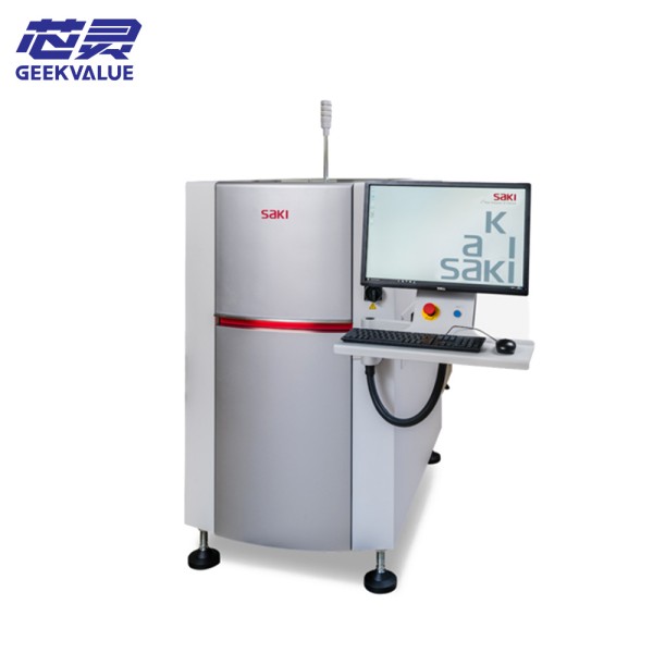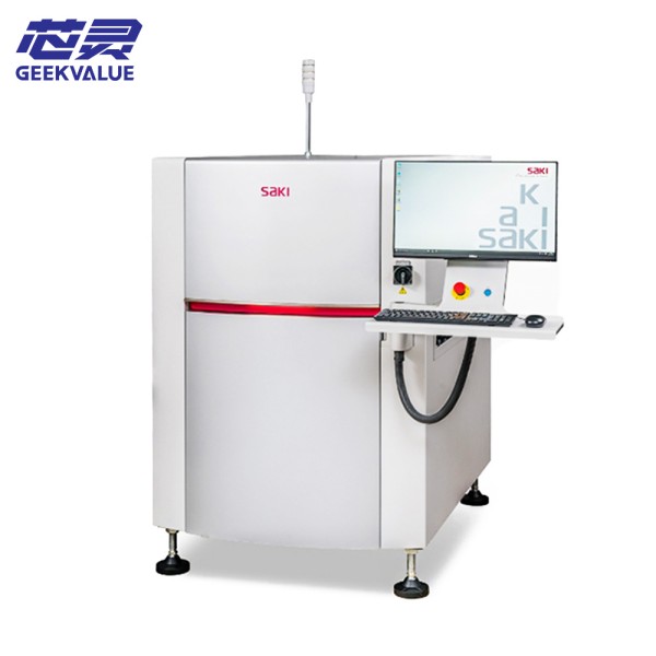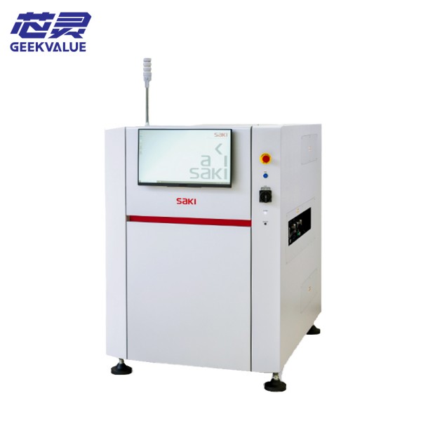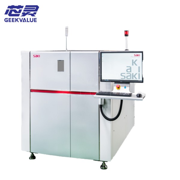
SAKI BF-TristarⅡ is a new generation of 2D automatic optical inspection system (AOI) launched by SAKI, designed for high-precision PCB assembly inspection. The equipment adopts a three-camera system architecture and combines multi-spectral lighting technology to achieve all-round inspection of SMT components, greatly improving inspection accuracy and efficiency.
2. Working principle
2.1 Optical imaging system
Three groups of high-resolution CCD cameras are used to simultaneously capture images from different angles (usually 0°, 30°, and 60°)
Each camera is equipped with an independent adjustable LED light source system that can combine multiple wavelengths (red light, blue light, white light, etc.)
Eliminate detection blind spots through multi-angle imaging and improve the detection reliability of complex components (BGA, QFN, etc.)
2.2 Image processing flow
Image acquisition: three cameras synchronous shooting
Image preprocessing: automatic white balance, shadow correction, noise elimination
Feature extraction: edge detection, grayscale analysis, pattern matching
Defect determination: intelligent classification based on rules and AI algorithms
Result output: NG mark, data upload to MES
3. Technical specifications
Project Parameters
Detection accuracy Minimum detectable component 0201, solder joint detection accuracy ±15μm
Detection speed Maximum 0.05 seconds/detection point (theoretical value)
PCB size Maximum 510×460mm (standard type)
Camera system 3×5 megapixel CCD, frame rate 30fps
Light source system Multi-color LED combination light source (red/blue/white/IR)
Repeat accuracy ±5μm
Communication interface SECS/GEM, TCP/IP, RS-232
4. Core features
4.1 Three-camera collaborative detection
0° camera: detect component body and logo
30° camera: detect solder joint contour
60° camera: detect solder joint surface status
Three-view data fusion, eliminating single-view detection blind spot
4.2 Intelligent detection algorithm
Deep learning model: automatically learn OK/NG sample features
Dynamic threshold adjustment: automatically optimize parameters according to process changes
Virtual measurement: calculate 3D parameters such as component height and volume through images
4.3 Efficient production adaptation
Dual track design: detection and upper and lower boards are carried out simultaneously
Quick line change: program switching time <30 seconds
Intelligent re-inspection: automatically mark suspicious points to reduce manual re-inspection
5. Precautions for use
5.1 Environmental requirements
Temperature: 20±5℃
Humidity: 40-70%RH
Vibration: <0.5G
Lighting: Avoid direct strong light
5.2 Operation specifications
Power-on process:
Warm up for 10 minutes
Perform automatic calibration
Confirm the uniformity of the light source
Daily inspection:
Sampling every 2 hours to verify the inspection stability
Regularly clean the carrier positioning pins
Program management:
A standard inspection library must be established for new models
Regularly back up program parameters
6. Common errors and handling
Error code Fault description Solution
E101 Camera communication timeout 1. Check the camera connection cable
2. Restart the camera power
E205 Light source abnormality 1. Check the LED drive power supply
2. Replace the faulty LED module
E307 Motion control error 1. Check the servo drive
2. Clean the guide rail
E412 Image processing timeout 1. Optimize the inspection parameters
2. Upgrade the software version
E503 Data communication interruption 1. Check network connection
2. Restart communication service
7. Maintenance method
7.1 Daily maintenance
Daily:
Clean optical window (use special cleaning kit)
Check air source pressure (if applicable)
Confirm conveyor belt tension
Weekly:
Calibrate light source intensity
Clean linear guide
Back up system parameters
7.2 Regular maintenance
Monthly:
Replace filter cotton
Check camera focus
Lubricate mechanical parts
Quarterly:
Deep calibration of optical system
Replace aged LED module
Check electrical system insulation
7.3 Annual maintenance
Performed by manufacturer engineers:
Full calibration of optical system
Mechanical structure accuracy detection
Control system firmware upgrade
8. Summary of technical advantages
Detection capability: Three-camera system realizes zero-dead-angle detection
Detection accuracy: Sub-pixel analysis algorithm
Detection efficiency: Parallel processing architecture improves throughput
Adaptability: Intelligent algorithm adapts to process fluctuations
Scalability: Supports online connection with 3D detection system
9. Application suggestions
High-density board: It is recommended to use with SPI
Flexible board: A special carrier is required
Automotive electronics: It is recommended to improve the testing standards
Consumer electronics: The testing speed can be optimized