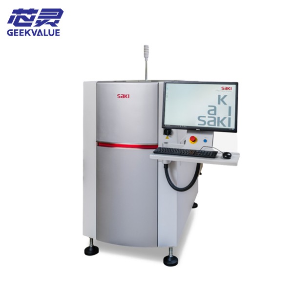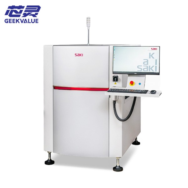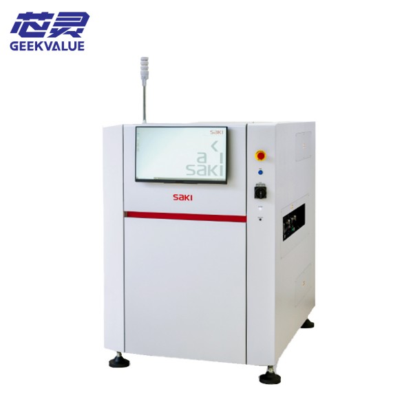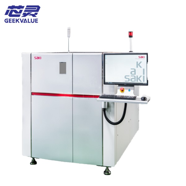
SAKI BF-LU1 is a high-performance two-dimensional automatic optical inspection equipment (AOI) dedicated to the quality inspection of PCB (printed circuit board) in SMT (surface mount technology) production lines. The equipment uses high-resolution optical imaging + AI intelligent algorithm to quickly identify problems such as solder joint defects, missing parts, wrong parts, and polarity errors to ensure quality control of the electronic assembly process.
2. Main specifications
Item Parameter
Detection technology High-resolution two-dimensional color imaging (multi-angle LED light source)
Detection object PCB solder joints (solder paste, BGA, QFP, etc.), SMD components (resistors, capacitors, ICs, etc.)
Optical resolution Up to 10μm/pixel (depending on lens configuration)
Detection speed 500~2000 components/hour (depending on PCB complexity)
Maximum PCB size 510mm × 460mm (standard model)
Light source system Multi-color LED ring light source (red/green/blue/white light, adjustable angle and brightness)
Software function Support CAD data import, automatic component matching, SPC data analysis, MES communication
Communication interface SECS/GEM, TCP/IP, support integration with MES/PLC system
3. Core features
(1) High-precision optical imaging
Adopt high-resolution CCD camera with multi-angle LED light source to ensure clear imaging of solder joints and components.
Supports red, green, blue and white light combination to enhance the contrast of different materials (such as solder and plastic components).
(2) Intelligent detection algorithm
Based on AI machine learning, automatically identify solder joint defects (low tin, high tin, bridge, cold solder joint, etc.).
(3) Flexible programming and automation
Support CAD file import, automatically generate detection programs, and reduce manual setting time.
(4) Efficient production integration
Can be linked with SMT placement machine, reflow soldering, and MES system to achieve real-time defect feedback and automatic sorting.
4. Main functions
(1) Solder joint detection
Solder paste printing detection (low tin, high tin, offset, bridge).
BGA/QFN solder joint detection (cold solder joint, missing ball, offset).
(2) Component detection
Missing components, wrong parts, reverse polarity, offset, monument.
(3) Data management
Storage of detection results, SPC trend analysis, and NG/OK data export.
Support barcode scanning to achieve PCB traceability.
(4) Production line linkage
Communicate with MES system to achieve automatic sorting or alarm shutdown.
5. Operation precautions
(1) Environmental requirements
Temperature: 15~30℃ | Humidity: 30~70% RH
(2) PCB placement
Ensure that the PCB is flat and fixed to avoid warping that affects imaging.
The conveyor track must be kept clean to prevent jamming.
(3) Light source calibration
Check the uniformity of the light source when starting the machine every day, and perform white balance calibration if necessary.
(4) Software settings
Select a dedicated inspection template according to the component type (BGA, CHIP, etc.) and optimize the inspection parameters.
(5) Safe operation
It is prohibited to adjust the camera focus at will, and it must be operated by trained personnel.
6. Common faults and solutions
Fault phenomenon Possible cause Solution
Blurred image/uneven brightness Lens contamination/aging of light source/focus offset Clean the lens, replace the light source, and recalibrate the focus
False alarm rate is too high Detection threshold is set too strictly/light source angle is not appropriate Optimize algorithm parameters and adjust light source angle
Transmission track is stuck Foreign objects on the track/sensor failure Clean the track and check the photoelectric sensor
Software crash/no response Insufficient memory/program conflict Restart the software, release memory, and update the version
Communication failure (MES/PLC) Loose network cable/protocol configuration error Check network connection and reconfigure communication protocol
7. Maintenance method
(1) Daily maintenance
Clean the lens and light source surface (use dust-free cloth + alcohol).
Check whether the transmission track is smooth and remove residual tin slag.
(2) Weekly maintenance
Calibrate light intensity and white balance.
Back up detection program and system parameters.
(3) Monthly/quarterly maintenance
Check whether the camera fixing screws are loose.
Clean or replace the heat dissipation filter