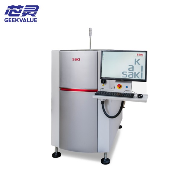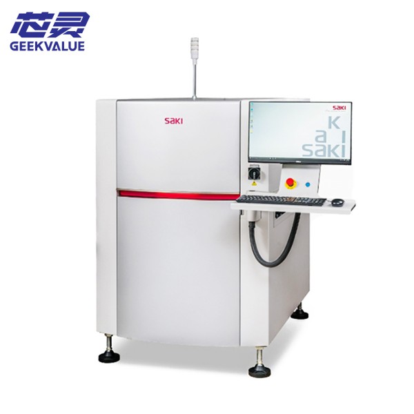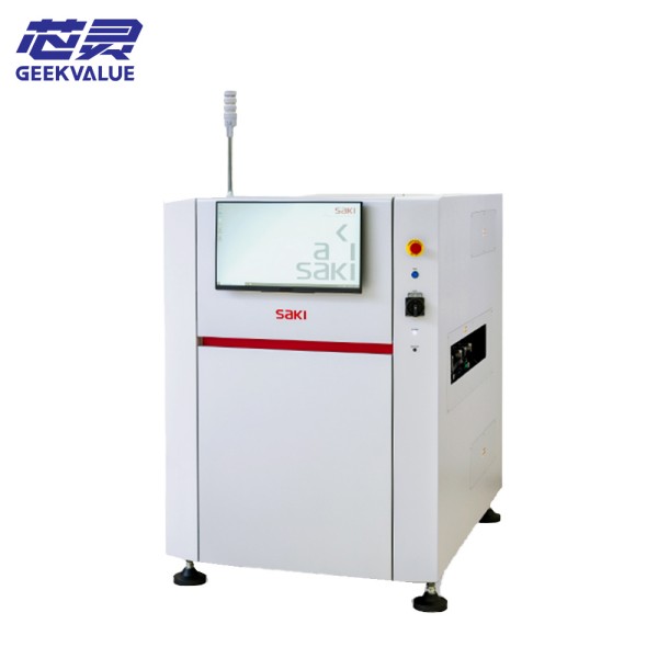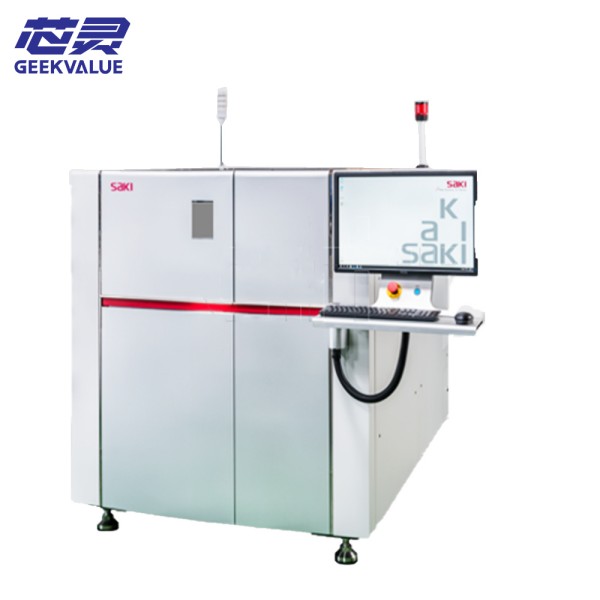
SAKI 3Di MS2 is a high-performance 3D automatic optical inspection (AOI) equipment designed for SMT (surface mount technology) production lines and used for high-precision soldering quality inspection during PCB (printed circuit board) assembly.
2. Main technical specifications
1. Hardware specifications
Project Specifications
Detection method 3D multi-angle imaging + AI intelligent detection
Maximum PCB size 510mm × 460mm (larger size can be customized)
Minimum detection element 01005 (0.4mm × 0.2mm)
Z-axis resolution ≤1μm
Detection speed Maximum 1,500 boards/hour (depending on the complexity of the PCB)
Light source system Multi-color LED structured light source, programmable control
Camera system High-resolution CCD camera, multi-angle shooting
Height measurement range 0-10mm
Height measurement accuracy ±5μm
2. Software specifications
Project Specifications
Operating system Windows 10/11 (64-bit)
Detection algorithm AI deep learning + traditional image processing
Programming method Graphical interface, support CAD data import
Data output CSV, XML, IPC-CFX (support MES docking)
Communication protocol SECS/GEM, TCP/IP
3. Core advantages
1. Ultra-high precision 3D detection
Adopt Multi-angle 3D imaging, accurate measurement of key parameters such as solder paste height, component offset, coplanarity, etc.
Can detect 01005 ultra-small components, adapt to the detection needs of high-density PCB boards.
2. AI intelligent algorithm reduces the false positive rate
Built-in deep learning algorithm, automatically learn normal welding characteristics, reduce false calls.
Support adaptive parameter optimization to adapt to different production processes.
3. High-speed detection, improve production efficiency
The detection speed is up to 1,500 boards/hour to meet high production capacity requirements.
Parallel computing optimization, shorten data processing time.
4. Flexible adaptation to different production needs
Can expand multi-camera configuration to adapt to different PCB sizes and detection requirements.
Support offline programming (OLP) to reduce production line downtime.
5. User-friendly and easy to operate
Graphical programming interface, lower the operating threshold.
One-click calibration, simplify equipment maintenance.
IV. Operation precautions
1. Power on and initialization
✅ Correct operation:
Ensure that the equipment is placed horizontally to avoid vibration affecting the detection accuracy.
Before powering on, check whether the power supply, air source, and data cable are connected normally.
After completing the system self-test, perform a reference calibration (recommended once a week).
2. PCB detection settings
✅ Correct operation:
Ensure that the PCB board is clean and dust-free to avoid misjudgment.
Adjust the track width to match the PCB size.
Select the correct detection program to avoid parameter errors.
3. Safe operation
Do not open the protective cover during operation to avoid mechanical damage.
Press the emergency stop button (E-Stop) in an emergency.
Regularly check whether the safety sensor is working properly.
5. Common fault information and solutions
Fault phenomenon Possible cause Solution
Blurred/missing image Lens contamination, abnormal light source Clean the lens, check the brightness of the light source
PCB transmission card board Track width setting error, loose belt Adjust the track, check the belt tension
Increased false alarm rate Detection parameters are not optimized, ambient light interference Recalibrate, optimize detection parameters
Software crash System file corruption, insufficient memory Restart the system, contact technical support
Communication abnormality Network connection failure, protocol mismatch Check the network cable, confirm the MES settings
6. Maintenance method
1. Daily maintenance
Daily:
Clean the surface of the equipment and the transmission track.
Check whether the air circuit and power supply are normal.
Weekly:
Clean the optical lens (use dust-free cloth + special cleaning fluid).
Check the belt tightness.
2. Regular maintenance
Monthly:
Back up the detection program and data.
Calibrate the light source and camera system.
Quarterly:
Replace wearing parts (such as belts, filters).
Check whether the mechanical structure is loose.
3. Annual professional maintenance
It is recommended that SAKI certified engineers perform:
Optical system precision calibration.
Mechanical structure precision inspection.
Conclusion
SAKI 3Di MS2 has become an important quality control equipment for modern SMT production lines with its high-precision 3D detection + AI intelligent algorithm. Through standardized operation + regular maintenance, equipment performance can be maximized, misjudgment can be reduced, and production efficiency can be improved. It is recommended that users establish a complete equipment management process and maintain communication with SAKI technical support to ensure long-term stable operation.