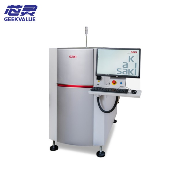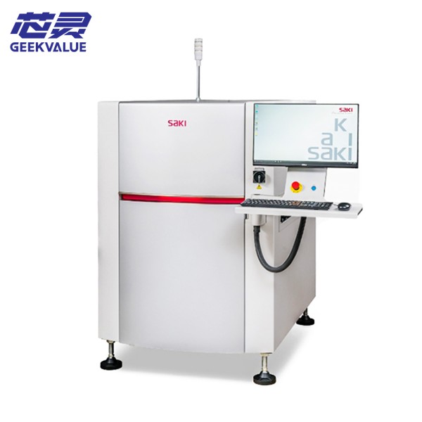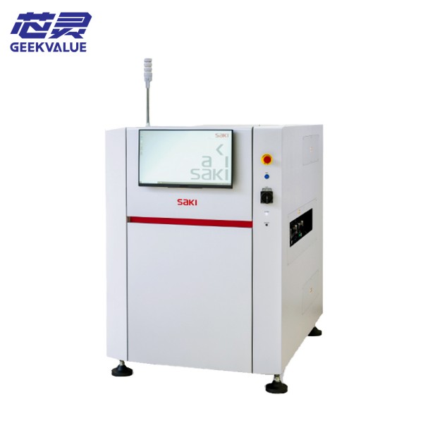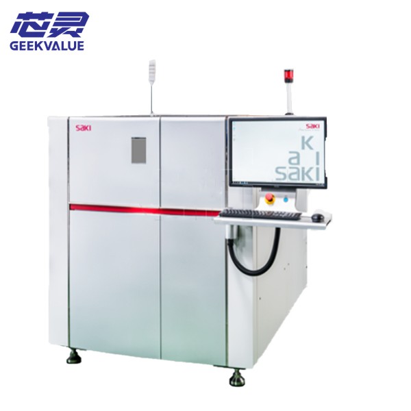
SAKI 3Di MD2 is a high-performance 3D automatic optical inspection (AOI) equipment launched by SAKI of Japan. It is designed for modern electronic manufacturing and is used for high-quality inspection during the assembly process of printed circuit boards (PCBs).
2. Main technical specifications
Hardware specifications
Imaging system: Multi-angle high-resolution CCD camera combination
Light source system: Multi-color LED structured light source, programmable control
Z-axis resolution: up to 1μm level
Detection speed: up to 1,200-1,500 boards per hour (depending on board size and complexity)
Maximum board size: 510mm × 460mm (larger sizes can be customized)
Minimum component size: 0201 (0.25mm × 0.125mm) or smaller
Height measurement range: 0-10mm
Height measurement accuracy: ±5μm
3. Core features and advantages
1. Advanced 3D imaging technology
SAKI 3Di MD2 uses patented 3D imaging technology to obtain component height information through multi-angle shooting and structured light source, and can accurately measure solder paste volume, component coplanarity and welding quality.
2. High-speed and high-precision detection
The equipment uses optimized optical paths and high-speed image processing algorithms to achieve fast detection without sacrificing accuracy, meeting the needs of high-capacity production lines.
3. Intelligent defect recognition
The built-in AI algorithm can learn normal welding characteristics and automatically identify various welding defects such as bridging, cold soldering, insufficient tin, component tombstones, etc., greatly reducing the false alarm rate.
4. Flexible system configuration
Different resolution cameras can be selected according to customer needs, and the detection angle or expansion board processing capacity can be increased to meet diverse production needs.
IV. Operation precautions
1. Power on and initialization
Make sure the equipment is placed on a level and stable workbench
Check all cable connections before powering on to ensure they are secure
After the system starts, wait for the self-test procedure to complete
Perform calibration regularly (recommended once a week or as required by production)
2. Daily operation
Ensure that the PCB to be inspected is clean and dust-free to avoid misjudgment
Check whether the width setting of the conveyor track matches the PCB board
Confirm that the inspection program is correctly selected
Observe the equipment operation status indicator
3. Programming precautions
After importing CAD data, be sure to check the component position and parameters
For key components, more stringent inspection parameters can be set
Save the inspection programs for different products and establish a program library
V. Common fault information and solutions
1. Image acquisition problems
Fault phenomenon: blurred or missing image
Possible causes: lens contamination, abnormal light source, camera failure
Solution:
Clean the optical components (use special cleaning tools)
Check the light source brightness setting
Recalibrate the camera
2. Conveyor system failure
Failure phenomenon: board stuck or poor transmission
Possible causes: improper track width setting, loose belt, sensor failure
Solution:
Adjust track width
Check and adjust belt tension
Clean or replace sensor
3. Abnormal test results
Failure phenomenon: sudden increase in false alarm rate
Possible causes: process parameter changes, improper program settings, ambient light interference
Solution:
Check actual process parameters
Re-optimize the test program
Ensure stable lighting around the equipment
VI. Maintenance methods
1. Daily maintenance
Cleaning work:
Clean the equipment surface and conveyor track daily
Clean optical components weekly (use a special cleaning kit)
Inspection items:
Check the lubrication of each moving part
Confirm that all fasteners are not loose
Check cable connection status
2. Regular maintenance
Monthly maintenance:
Fully clean the optical system
Check the consistency of light source brightness
Quarterly maintenance:
Replace wearing parts (such as belts, filters, etc.)
Fully calibrate the system
3. Annual professional maintenance
It is recommended that professional maintenance be performed by SAKI certified engineers every year, including:
Optical system precision calibration
Mechanical system accuracy check
Software system comprehensive diagnosis
VII. Optimization use suggestions
Environmental control: Keep the equipment running in an environment with a temperature of 23±3°C and a humidity of 40-70%RH
Data management: Regularly back up the detection program and system parameters
Software update: Regularly update the detection algorithm and system software
Conclusion
As a key equipment for modern electronic manufacturing quality control, the high performance and reliability of the SAKI 3Di MD2 3D AOI system have been widely recognized by the industry