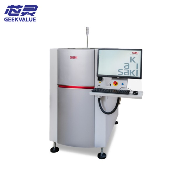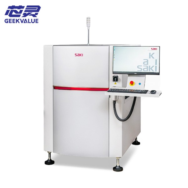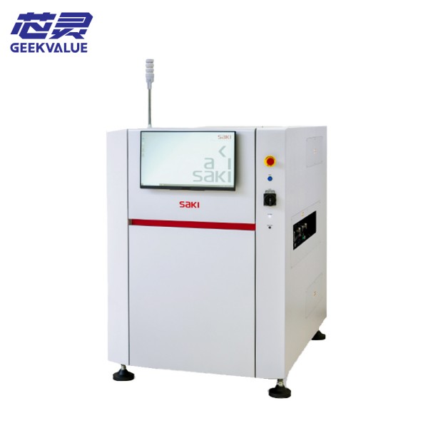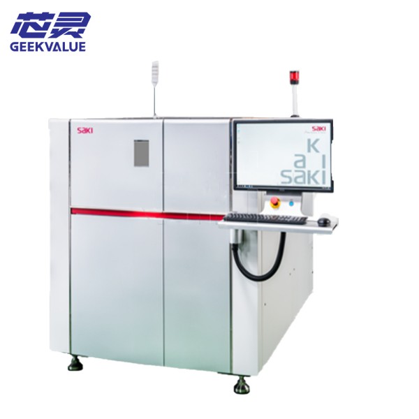
SAKI 3Di-LS3 is a high-performance 3D automatic optical inspection equipment (AOI) designed for the electronics manufacturing industry to detect welding defects (such as short circuits, cold solder joints, offsets, etc.) during PCB assembly. It uses laser scanning technology and multi-angle optical imaging to achieve high-precision and high-speed 3D inspection.
2. Main specifications
Item Parameters
Detection technology Laser scanning + multi-angle optical imaging (3D measurement)
Detection objects PCB solder joints, components (CHIP, QFP, BGA, etc.)
Detection accuracy Vertical resolution: ≤1μm, horizontal resolution: ≤10μm
Scanning speed Up to tens of thousands of measurement points per second (depending on the complexity of the PCB)
PCB size Supported maximum board size: usually up to 510mm × 460mm (specific models need to be confirmed)
Programming method Graphical interface, support CAD data import, automatic component matching
Communication interface Support SECS/GEM, TCP/IP, integrated with MES system
3. Core functions
3D solder joint detection: Reconstruct the height profile of the solder joint through laser scanning, and detect defects such as insufficient tin, excessive tin, and bridging.
Component missing/offset detection: Identify component position, polarity, wrong parts, etc.
Multi-angle optical inspection: Combine 2D images with 3D data to improve the control of false positive rate.
Statistical process control (SPC): Generates inspection reports in real time, supports data traceability and analysis.
Adaptive inspection algorithm: can learn normal solder joint morphology and reduce false alarm rate.
4. Operation precautions
Environmental requirements:
Temperature: 20±5℃, humidity: 30-70% RH, avoid vibration and direct light.
PCB placement:
Ensure that the PCB is flat and fixed on the carrier to avoid warping affecting the laser scanning accuracy.
Calibration and maintenance:
Laser calibration and optical system focal length calibration are required for daily startup.
Safe operation:
Do not look directly at the laser light source, and do not open the protective cover when the equipment is running.
5. Common faults and solutions
Fault phenomenon Possible cause Solution
The laser scanning image is blurred. The lens is contaminated or the focal length is offset. Clean the lens and recalibrate the focal length.
The false alarm rate is too high. The detection parameters are set too strictly or the light source is uneven. Adjust the threshold parameters and check the consistency of the light source brightness.
Communication failure (connection with MES is interrupted). Network configuration error or interface is loose. Check the network cable/IP settings and restart the communication service.
Abnormal movement of the robot arm. The guide rail is contaminated or the motor fails. Clean the guide rail and lubricate it, and contact after-sales to check the motor.
6. Maintenance method
Daily maintenance:
Clean the optical lens (with dust-free cloth + alcohol).
Check the air source pressure (if applicable).
Weekly maintenance:
Clean the carrier and conveyor track to avoid dust accumulation.
Calibrate the laser height sensor.
Regular maintenance (quarterly):
Replace aging light sources (such as LED light strips).
Back up system parameters and detection procedures.
7. Additional instructions
Software upgrade: It is recommended to contact SAKI technical support regularly to obtain the latest algorithm updates.
Spare parts: Laser modules, optical lenses, carriers, etc. must use original accessories.
If you need a more detailed technical manual or fault code list, it is recommended to refer to SAKI official documents or contact an authorized service provider.
")