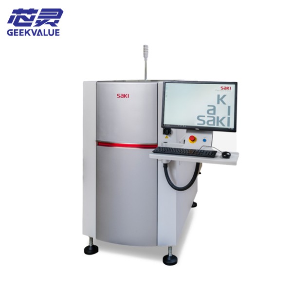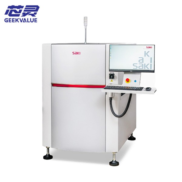
SAKI 3Di-MS3 is a new generation of 3D automatic optical inspection (AOI) equipment, designed for high-precision PCB assembly (PCBA) inspection. The equipment uses multi-spectral imaging + 3D laser scanning technology, combined with AI deep learning algorithms, to accurately detect the welding quality of complex packages such as 01005 ultra-small components, BGA, QFN, CSP, etc., meeting the needs of high-reliability industries such as automotive electronics, medical equipment, and aerospace.
2. Core Specifications
1. Optical Detection System
Parameters Specifications
Detection Technology 3D Laser Triangulation + Multi-angle Color Imaging
Highest Resolution 16MP (4928×3264 Pixels)
Minimum Detectable Component 008004 Package (0.25×0.125mm)
Z-axis Measurement Accuracy ±3μm
Detection Speed ≤0.3 Seconds/Detection Point
Light Source System Programmable Multi-angle RGB-IR Hybrid Light Source
2. Mechanical Performance
Parameters Specifications
Maximum PCB Size 610mm×510mm (optional up to 800mm)
Stage Positioning Accuracy ±3μm
Motion System Linear Motor Drive + Air Bearing
Z-axis Adjustment Range 0-60mm (Autofocus)
3. Intelligent software system
Detection algorithm: CNN convolutional neural network + traditional rule detection
Detection items:
Solder point defects (false solder joints/short circuits/insufficient tin)
Component defects (missing parts/wrong parts/offset/tombstones)
3D morphology measurement (coplanarity/solder paste volume)
Data interface: support SECS/GEM, MES docking
Report output: PDF/Excel/custom format
4. Environmental requirements
Parameters Requirements
Working temperature 18-26°C (constant temperature recommendation)
Humidity range 40-60%RH
Power requirements 220V±5%/50Hz/3kVA
Compressed air 0.5MPa (clean and dry)
Equipment weight About 1500kg
III. Key usage specifications
1. Key points for safe operation
Laser safety: Do not look directly into the laser beam (Class 2M laser)
Sports protection: Emergency stop button test at least once a week
Static electricity protection: Wear an anti-static bracelet when touching PCB
2. Standardized operation process
Startup procedure:
Turn on the main power → Start the industrial computer → Initialize the motion system (about 90 seconds)
Perform daily calibration (including: optical calibration/height reference calibration)
Test preparation:
PCB positioning requires the use of special fixtures (tolerance ±0.1mm)
New models need to establish a 3D component library (it is recommended to collect ≥5 samples)
Parameter optimization:
For highly reflective components (such as QFN), multi-spectral fusion detection needs to be enabled
For densely pinned devices, it is recommended to use a local scanning strategy
3. Maintenance system
Cycle Maintenance items Standard
Daily Optical window cleaning Use a special dust-free cloth + optical cleaner
Weekly Guide rail lubrication and maintenance Use NSK LGHP2 grease
Monthly Laser power detection Attenuation rate ≤5%/year
Quarterly Comprehensive precision calibration Use NIST certified standard board
IV. Typical troubleshooting solutions
1. Mechanical system failure
Failure phenomenon: abnormal noise/positioning deviation of the stage movement
Possible causes:
Insufficient lubrication of the guide rail
Encoder contamination
Servo motor overheating
Solution:
Failure handling process
1. Perform manual lubrication procedure
2. Clean the encoder with anhydrous ethanol
3. Check the operating status of the cooling fan
4. Perform grid compensation calibration
2. Optical system failure
Failure phenomenon: 3D point cloud data abnormality
Diagnostic steps:
Check the laser power supply voltage (24V±0.5V)
Verify the calibration board measurement value
Check ambient light interference
Emergency measures:
Temporarily enable 2D detection mode
Adjust laser power (80-120% range)
V. Advanced application skills
1. Optimization of special material detection
Ceramic substrate: Enable infrared band detection (optional IR module required)
Flexible PCB: Use segmented scanning mode (reduce mechanical stress)
2. Improve detection efficiency
Parallel processing technology:
Optimization example
Traditional mode: Sequential detection → 0.5 seconds/point
Optimization mode: Regional parallel → 0.2 seconds/point
Intelligent skip inspection strategy: automatically reduce the inspection density for the tested qualified areas
VI. Technical support system
Remote diagnosis: support VPN real-time connection (requires advance filing)
Spare parts replacement cycle:
Laser: ≥20,000 hours
Industrial camera: ≥50,000 hours
Calibration service: It is recommended to calibrate the original factory once a year
")